

BASICS OF BALANCING
The static imbalance (U, [g.mm]) causes a position difference (e, [mm]) between the centre of gravity and the axis of rotation of the toolholder.
This imbalance causes a centrifugal force that has negative effects both on the machine tool and on the toolholders themselves.
| U = e x Mtoolholder |
Where : U = static imbalance in gr/mm |
|
F = U x ω2 x 10⁻⁶ |
Where : F = force [N] |
The imbalance is compensated by adding or removing the mass.
Dynamic imbalance involves a difference in position between the main axis and the rotation axis which generates harmful vibrations.
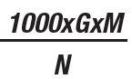
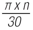
The ISO1940 standard (relating to balancing) determines the allowable unbalance (U, [g.mm]) calculable as:
|
Uper: |
Where : G = balancing grade [mm/s] M = mass [Kg] n= rotation speed [revolutions/min] |
BENEFITS OF BALANCING
• Reduced vibrations during the machininig.
• Better roughness of the workpiece.
• Increase of the insert, bit or mill
By balancing the tool holder you will have greater stability during processing, thanks to the correct weight distribution.
This is the reason why we prefer to balance our tool holders.
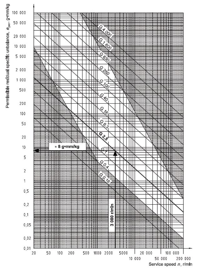
The graph below shows how the e value is detected.
The toolholder rotation speed is indicated with n on the X axis.
The permissible residual specific unbalance is indicated with e per g.mm/kg on the Y axis.
The chart is used as follows:
1. Select, on the X axis, the number of revolutions that the toolholder must use during machining.
Example: 3000 r/min
2. With a straight line, increase vertically in the graph, until one of the oblique lines intersects indicating the desired degree of tolerance.
Usually the most used tolerances are G6.3 and G2.5 in the example shown, the tolerance G2.5 has been selected.
3. From the point of intersection between the vertical and oblique lines, draw a horizontal line and note the value shown on the Y axis.
4. Multiply the value found on the Y axis by the weight of the toolholder in Kg.
5. The result is the allowable imbalance for the toolholder and for machining.